The content of this page has not been vetted since shifting away from MediaWiki. If you’d like to help, check out the how to help guide!
Overview
This plugin provides a more impartial, reproducible, and mathematically rigorous way of calculating interplanar spacing, which makes it more accurate than calc dSpace. It is also easier to use on diffraction patterns where it is hard to tell which reflections originate at like planes in the crystal. Get dSpace helps the user figure this out.
How it Works
A threshold is applied to the diffraction pattern that the user can manipulate so it suites their image. The centroids of the thresholded spots are then found, and the d-spacing is calculated for each spot as the inverse of the distance from the direct beam.
If you did not use a beamstop for image capture, the direct beam spot corresponds to one of the spots in the image, and the user tells the plugin which spot to use. If a beamstop was used for image capture, then the user picks a pair of spots symmetric about the direct beam spot and the plugin finds the center from those two positions.
The plugin then makes an attempt at binning the measurements according to their d-spacing, and plots both the binned and averaged values along side measured values. This gives the user a chance to conceptualize and evaluate the results.
Directions
Getting Started
This is the window that opens up when you first start the plugin. All you need for the plugin to work is an opened diffraction pattern that is calibrated and saved as a .dm3 file. 
- Minimum diffraction spot size: is one less pixel than the number of pixels you choose as constituting a diffraction spot. It is good for ignoring cosmic rays that might be captured in your DP, and small fringe spots that sometimes show up near the edges of diffraction spots.
- Beamstop Status: choose the appropriate option regarding whether or not a beamstop was used to block the direct beam.
- Binning Size: this sets a value in the plugin that is used to distinguish between like planes (110, 101, and 011) and different planes (100, 110, 111,…).
- Display modes: these options allow the user to operate the plugin in three different modes. The Measurements mode does not give you a summary plot or table, which is convenient if you are optimizing your settings for a single DP. The Summary mode closes the two measurement windows (so you don’t have to) and only shows the summary table and plot. All leaves all four windows open, so you see everything.
- d-spacing list: yet a fifth window that you can enable, which allows you to view the list of d-spacing values in a text window on a single line.
- Ring Overlay: not shown in the image above, but a new option that draws circles on the diffraction pattern that correspond to the measurements made, and adds an inset with a list of d-values. See calc dSpace for more info.
Adjust Threshold
 Once you click the “OK” button on the first window. Your DP will be duplicated, and converted to 8-bit. The auto threshold routine is run and the usual threshold window appears. You can use the sliders to adjust thresholding levels to optimize your image. When you are happy with the thresholding, click the “OK” button on the window below to proceed.
This is a wait-for-user window that stalls the plugin until you are ready for it to move forward.
Direct Beam Spot
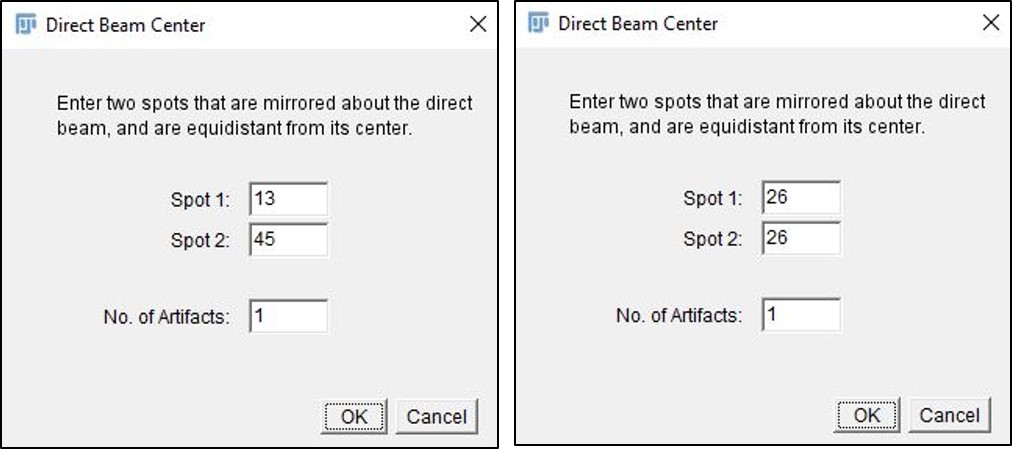
After you click “OK” to proceed, each diffraction spot is measured and labelled, and a new window pops up (shown below) that then asks you to help the software find the direct beam spot. This is the most critical part of the process because the center of the direct beam is the point from which all distances are calculated.  If you have not used a beamstop to cover the direct beam spot in your image, then a simpler window (not shown) appears that just asks you which label corresponds to the direct beam, and the centroid of that spot is used for the calculations. For example, in the image below, spot 26 is the direct beam spot.
If you have used a beamstop in your image, then you must enter the labels corresponding to a spot pair in the image that have mirror symmetry in any plane drawn through the direct beam center and normal to the image plane. For example, in the image below, spots 13 and 45 would be a good choice.
Finally, there is a box for artifacts in the image. Artifacts usually occur as a result of the beamstop or small spurious spots that form near the direct beam spot in lower contrast regions. The number entered in this box is the number of values that are trimmed from the list of d-spacing. Just remember you are removing your largest values of d.
For example, with the beamstop retracted, the direct beam will have a d-spacing of infinity, so it is an artifact that should be removed. The beamstop retracted option does this automatically, but it doesn’t let you remove more spots, to do that you can use the beamstop inserted option, and just enter the direct beam label twice.
Measurements
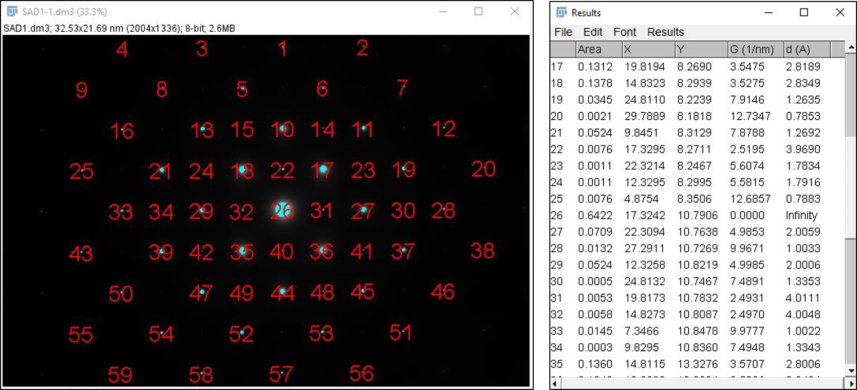
The image on the left is an example of a thresholded measured and labeled diffraction pattern. The table on the right lists the measurements made for each spot in the image that was larger than the minimum spot size set on the first window (“get dSpace”). The row numbers correspond to the labels in the image, which allows you to track the measurements and really probe the DP. Especially if you want to label the spots in a single crystal pattern like the one shown (strontium titanate) with the appropriate Miller indices.  If the Summary option is selected these windows will be closed automatically, but if the Measurements option is selected on the first window then only these windows will be displayed.
Results Windows
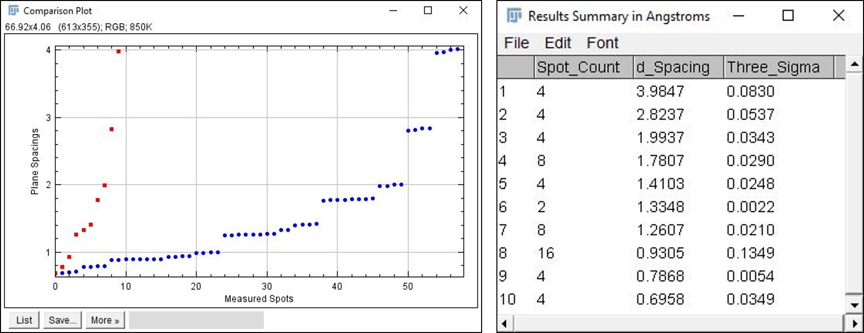
These windows make up the final step of the get dSpace plugin. The plot on the left compares the individual measurements for each spot (blue circles) in the image to the average values for like planes (red squares). This is where the binning size comes into play from before. In general, larger bin sizes are needed for larger d-values(>2.5 A), and smaller bin sizes are needed for smaller d-values (<2.5 A). The plot gives a nice visual representation of how successful the binning was, and the table gives a numerical representation of the same.  The table on the right summarizes the results for your sample. It lists the row number, the number of spots averaged to obtain the d-spacing (spot count), the d-spacing (in Angstroms), and the uncertainty in the measurement (in Angstroms). The uncertainty is obtained using the three sigma rule. The uncertainty should decrease with decreasing d-values.
If you see a larger value than expected and a high spot count then there might be different planes being treated as one. This is the case for row 7 in the example table. However, it is unlikely that this error will prevent me from indexing this list to STO. Keep in mind that the unique planes for most materials are the ones with larger d-values. Therefore, the larger d-spacings are more important for indexing, which is why there are two large binning size options and only one small option.
Image Requirements
You need to have a properly calibrated diffraction pattern for the calculations to work. Most TEMs use Gatan’s Digital Micrograph software for image collection. If you are using DM, then it is likely that this plugin will work right away, or will work with the help of your TEM technician.
The preferred image is a .dm3 file (Gatan’s format) that is properly calibrated in reciprocal space (see Gatan’s documentation). The easiest way to check this is that the scale bar in your images is displayed in DM with 1/nm units.
Tips
- Another way to verify your image calibrations have been done properly is to call up the image info window in imageJ (just type the letter “i”) and look for a line like this: root.ImageList.1.ImageData.Calibrations.Dimension.0.Units = 1/nm. If it = nm, then it won’t work.
- The plugin may not work right the first time you try to use it, this would be because you do not have the area measurement enabled. Running the plugin will set the measurements it needs, so if you redo your measurements with the circle tool, it should work the second time.