The content of this page has not been vetted since shifting away from MediaWiki. If you’d like to help, check out the how to help guide!
Overview
This plugin can be used to quickly calculate the interplanar spacing values (d) directly within imageJ without copying the results table to another program like Excel to then convert measurements into d-values, which saves you time. It is also remarkably easy to use, accurate, and robust for both spot and ring electron diffraction patterns.
How it works
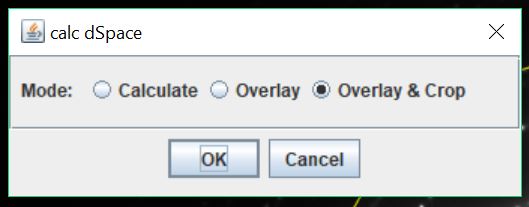
Use imageJ’s circle tool (shift + oval tool) to measure the spot/ring patterns concentric to the (000) direct beam. From the area measurement, the radius (G) is found. From G = 1/d in reciprocal space, the d-spacing is calculated for each measurement made. This plugin has three different modes in which it can operate.

The first, and most basic mode, is calculate where the calculated values for G and d are added to the imageJ Results window in new columns. G is in nanometers and d is in Angstroms. There is also a 2% error column, which is just 2 % of d in angstroms.
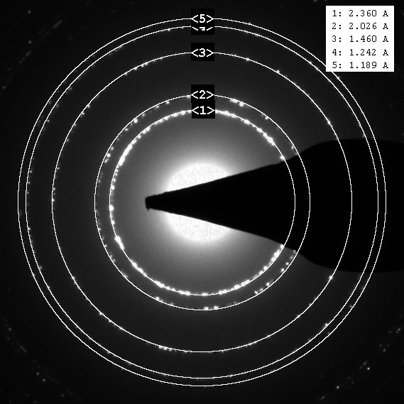
Overlay is the second mode, which draws the positions of the measurements made back onto the diffraction pattern image, and displays an inset with the calculated d-spacing values for each ring. It also labels the rings and d-spacing measurements in the inset so that there is traceability between the calculated values and the measurements made using the circle tool. This visual correlation between d spacing and measured rings is useful for indexing diffraction patterns, because the TEM operator can subjectively take ring intensity into account. For example, you may be deciding between two phases that have similar d-spacing lists, but different ring intensities. This helps determine which rings are the most intense in the patterns adding a data component that is sometimes lost in SAD analysis.
The final mode is Overlay & Crop, which is more of a publication-ready mode that actually crops the diffraction pattern down to the size of the measured region. This is more suitable for publication, as it zooms to the measured region and makes the image square. This image is best saved as a jpeg first and then saved as a tiff if that is the preferred format.

Image Requirements
You need to have a properly calibrated diffraction pattern for the calculations to work. Most TEMs use Gatan’s Digital Micrograph software for image collection. If you are using DM, then it is likely that this plugin will work right away, or will work with the help of your TEM technician.
The preferred image is a .dm3 file (Gatan’s format) that is properly calibrated in reciprocal space (see Gatan’s documentation). The easiest way to check this is that the scale bar in your images is displayed in DM with 1/nm units.
Strontium Titanate Example
The example below is from a single crystalline STO (strontium titanate) sample. It illustrates how the measurements should be made in order to ensure the plugin is calculating the d-spacing values accurately. Make your measurements working from the inner most spots/rings outwards.  The table on the left shows the raw imageJ measurements that were made by drawing a circle and pressing the “m” key on the keyboard. The table on the right is the result of the plugin. Just go to the TEM menu and select calc dSpace. The calculation is automatic.
  There are 3 new columns in the Results window: G, d, 2% error. The scalar component of the G vector in reciprocal space is found and measured in 1/nm since these are the image units. The d-spacing is listed in Angstroms, and the 2% error is just 2% of the d-spacing. While it is not an actual uncertainty measurement, it can help you index your sample.
Tips
- If you hold down both control and shift while clicking on one of the white squares on the circle and dragging, the circle expands and contracts concentrically.
- The centroid is there to display the x and y position of the center of the circles you are drawing. Use it to make sure it is at the center of the direct spot (000), and that it stays there throughout your measurements.
- Another way to verify your image calibrations have been done properly is to call up the image info window in imageJ (just type the letter “i”) and look for a line like this: root.ImageList.1.ImageData.Calibrations.Dimension.0.Units = 1/nm. If it = nm, then it won’t work.
- You can enable a somewhat useful text window that summarizes your results by opening up the plugin in a text editor and deleting the leading slashes on line 29.
- The plugin may not work right the first time you try to use it, this would be because you do not have the area measurement enabled. Running the plugin will set the measurements it needs, so if you redo your measurements with the circle tool, it should work the second time.