A Fiji plugin for the segmentation of 3D objects.
Enable the LimeSeg update site to get it.
Publication
Video tutorials
Probably the fastest to learn how to use LimeSeg at a basic level. You can find here a playlist containing all the tutorials. This playlist contains tutorials for:
- Single object segmentation
- Multiple objects segmentation
- Segmentation refinement
- Single object segmentation with multiple seeds
- An example of a C. Elegans embryo segmentation (one time point)
- Single object segmentation with a pre-defined shape
- Computing and displaying surface curvature
Presentation
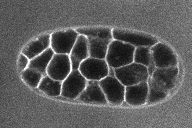
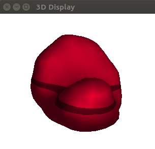
Test LimeSeg is a modular 3D segmentation plugin. It is a particle-based active contour method. It can segment objects from 3D images where 3D objects are labelled on their outline, like cells labeled on their membrane, as shown in the image below (source of the image : dub).
LimeSeg can be used with simple commands provided by the plugin (under Plugins › LimeSeg in ImageJ menu), or on a more advanced manner with scripting capabilities of ImageJ (macro commands of ImageJ 1.x or preferentially with groovy scripts).
Commands : basic usage
Single object segmentation
Sphere Seg command
The command Plugins>LimeSeg>Sphere Seg is the easiest way to use LimeSeg. It allows to segment a 3D object starting from a spherical seed. Here’s an example to show how to use it:
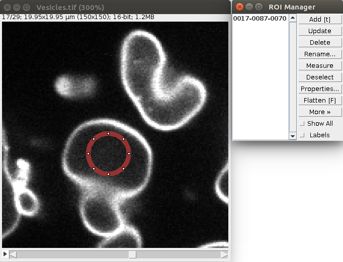
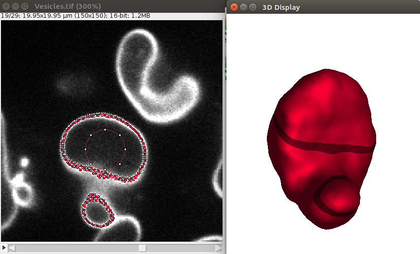
1. Open a sample vesicle image. To do this, do File>Import>URL.. and enter the address https://raw.githubusercontent.com/NicoKiaru/TestImages/master/Vesicles/Vesicles.tif
2. Draw a circular ROI that is contained within the vesicle And save it in the ROI manager with the t key or with Edit>Selection>Add To Manager (only this ROI should be contained in the ROI manager).
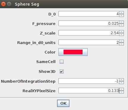
3. Execute the Sphere Seg command : Plugins>LimeSeg>Sphere Seg
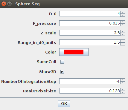
4. You need to provide the four most important parameters:
D_0: this parameter expressed in numbers of pixels (it can be a real value like 1.2 pixels) is the smallest feature size that you want LimeSeg to detect. A low value (~ 1 pixel) will lead to fine details being detected, at the cost of speed. A too high value will lead to important details being missed. The value is typically between 1 and >20 pixels. (More precisely,D_0is the equilibrium spacing between the particles used by LimeSeg to delineate the 3D shape.)F_pressure: is the “default pressure” exerted on the surface (also called balloon force in related active contour methods). A positive value will lead to expansion of the surface by default, while a negative value will lead to shrinking. Its typical range is [-0.03..0.03].Z_Scale: is the physical ratio of the spacing between slices (Z spacing) and between pixels (X or Y spacing). The vesicles were imaged with pixels of 133 nm and a z-spacing of 340 nm. Hence this parameter should be set to 340/133 ~ 2.54.Range in d0 units: is the size over which each particle will look for a local maximum. A value of 2 with aD_0of 2 means that a local maximum will be looked for within a layer of 2*2 = [-4..+4] pixels around the surface. Typical values are from 0.5 to >10.
5. Other parameters:
show 3D: if checked, displays a 3D view of the segmented objects. For more options, see #ref 3D viewer (TODO).same cell: this parameter is not important in this case, since only a single ROI is provided. It will become useful when multiple seeds are needed, see #ref multiple objects (TODO) and #single big objects.Optimisation steps: number of optimization steps. If set to -1, the optimization will take place until convergence is met.real size XY: the size of a XY pixel in physical units. Here a pixel is 133 nm. To get the volume and surface in microns squared and microns cubed units, set this parameter to 0.133.
To segment this demo image, please choose the parameters as in this image:
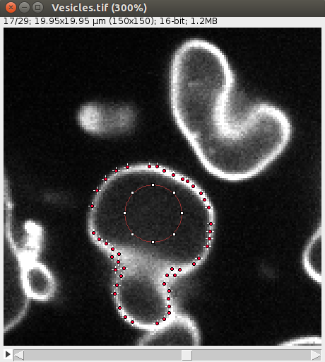
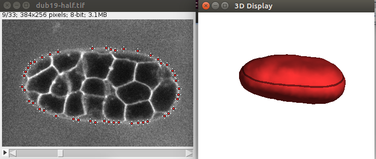
After convergence, you can go through the 2D image and you should see some points along the objects, like this:
Also the 3D viewer should give a 3D View of the vesicle:
Other outputs are provided as an ImageJ table: 
Cell_Name: each 3D object that LimeSeg generated is a “Cell” object. By default, these objects have a String identifier:Cell_0,Cell_1,Cell_2…Number of Surfels: number of surface elements in the generated 3D object. This number is also the number of vertex within the 3D Mesh.Center X,Y,Z: position of the center of mass of the object Vertexes, expressed in pixels for XY, and in slice number for Z (using IJ1 numbering)Frame: frame where the object has been segmentedChannel: Channel where the object has been segmentedMesh?: indicates where a mesh has been reconstructed from the object surfelsEuler characteristic: Euler characteristic of the reconstructed mesh. This value needs to be 2 for a simply closed surface, 0 for a torus, etc. If its value is not in accordance with your expectations, the surface and volume values will be wrong.Free edges: Number of free edges of the 3D reconstructed mesh. Should be equal to zero to trust the given surface and volume.Surface: Surface of the object in(XY_pixels)^2unitsVolume: Surface of the object in(XY_pixels)^3unitsReal Surface: Physical surface of the objectReal Volume: Physical volume of the object
Troubleshooting
- If the circle ROI is too small, the sphere will disappear immediately → make a bigger circular ROI.
- If the circle ROI is too big or not fully contained into the vesicle, the surface could leak outside → recenter the ROI.
- “the segmentation goes crazy and I’d like to stop it”. You can either execute the command
Plugins>LimeSeg>Stop Optimisation, or you can set a value different from -1 in the number of optimisation steps parameter (10000 steps is enough for this demo case).
Refining a segmentation result
It is possible to refine a segmentation by decreasing D_0 after a first roughly defined shape is found. Doing a first segmentation at a high D_0 and then decreasing it by refinement is usually faster than starting the segmentation at a low D_0 value. This can be done after a first segmentation by using the Plugins>LimeSeg>Coarsen/Refine command.
For instance, in the vesicle example:
- Right after the convergence is reached for
D_0 = 4, launch thePlugins>LimeSeg>Coarsen/Refinecommand with these parameters: Choose the following parameters:D_0_ini = 4;D_0_end = 2;range_in_D_O_units=2. - After the command is finished, you need to resume the segmentation until convergence is newly reached. To do this, execute the command
Plugins>LimeSeg>Resume Seg. You can keepF_pressureto zero, since no bias is required anymore, and set the real size of the pixel as before (0.133).
The shape is now more precise, as you can see in the 2D view and in 3D:
Alternative ways to segment a single object: multiple spheres and skeletons
If the object you want to segment is tortuous or big, starting with a single spherical may not give good results. Here are two alternative ways to segment a single object.
Starting with multiple spherical seeds
The sample image accessible here https://raw.githubusercontent.com/NicoKiaru/TestImages/master/ER/ER-FIB-SEM-Small.tif (use File>Import>URL) is a piece of endoplasmic reticulum and is pretty tortuous. While you may get a correct result with one circular ROI as a seed and with the Sphere Seg command (D_0 = 2 and F_pressure=0.02 gives good results), one can also store several circular ROI in the ROI manager at different places in the piece of ER. Lauching the Sphere Seg command and checking the same Cell checkbox will lead to a faster segmentation. When the different seeds meet, they will merge into a single surface.
For instance for three spherical seeds:
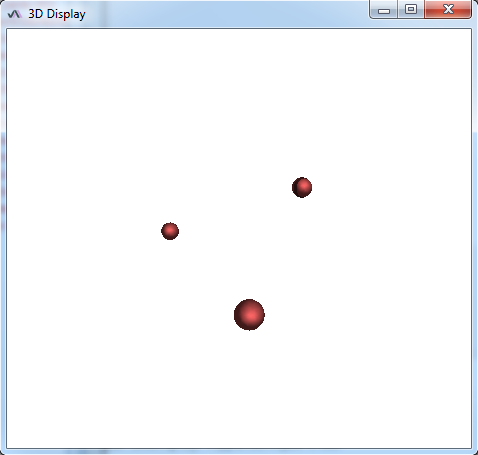
Final result:
Starting with a ROI skeleton
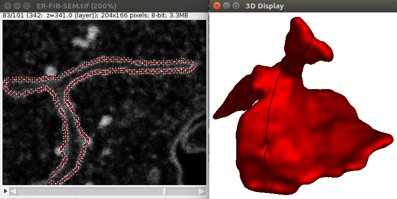
It is possible to define more precisely the seeds used to segment images. This can be useful for instance to predefine the structure you want to segment. Let’s show how this works through an example, like the segmentation of the contour of the CElegans embryo:
1. Download a 3D C. Elegans embryo image File>Import>URL.. from here which is a timepoint extracted from the full dub dataset.
2. Using a few ROIs approximately define the contour of the embryo at certain slices, like in the image shown above:
You need to begin and end with a single point ROI, otherwise the shape will not be closed. Also, the ROIs need to be drawn clockwise and should starts always at the same angle (start on top for instance).
3. Launch the Plugins>LimeSeg>Skeleton Seg command, without anything else in the ROI manager. Using the parameters D_0=10, F_pressure = 0, range_in _d0_units=2 and Z_scale=3.5 should give correct results, like shown below:
Multiple objects segmentation
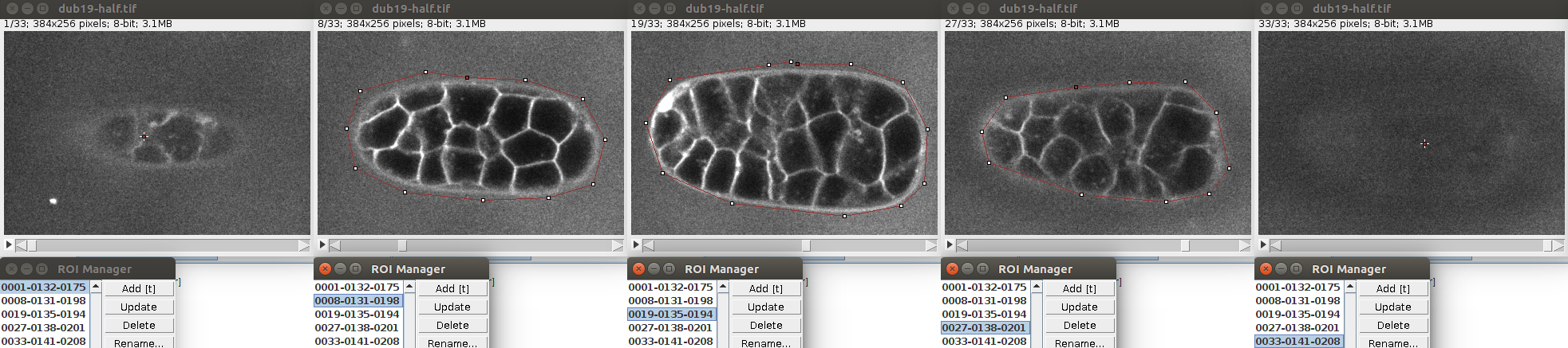
It is possible to segment multiple non overlapping objects with LimeSeg. The most basic way to do this is through the Sphere Seg command. In order too to an example, you can open the test image of c.elegans with File>Import>URL. This is a timepoint extracted from this dataset.
Like previously, you can store a single circular ROI in the ROI manager and launch the Sphere Seg command. This set of parameters work nicely:
D_0 = 4F_Pressure = 0.015Range_in_D0_units = 1.5ZScale=3.5
In this kind of image, you’d probably like to segment multiple cells. You can do this one at a time, but sometimes one segmented surface will leak onto another, because the frontiers are sometimes not well defined. One way to avoid this is to segment multiple cells in parallel and avoid surface overlap. LimeSeg can do this : you can define several seeds defining several objects. In this case, the surfaces will repel each other, a bit resembling watershed methods in that aspect.
You can define multiple seeds (one per cell) simply by storing multiple circular ROIs in the ROI manager. Like in this image:
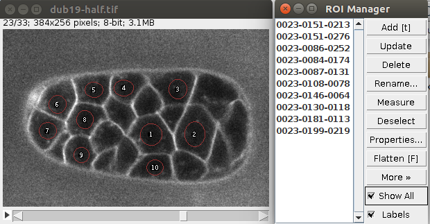
Of course the seeds can be located at different planes.
You can then launch the Plugins>LimeSeg>Sphere Seg command with the previously defined parameters, but be sure to uncheck the sameCell checkbox (otherwise surfaces will merge):
You should obtain an image similar to this:
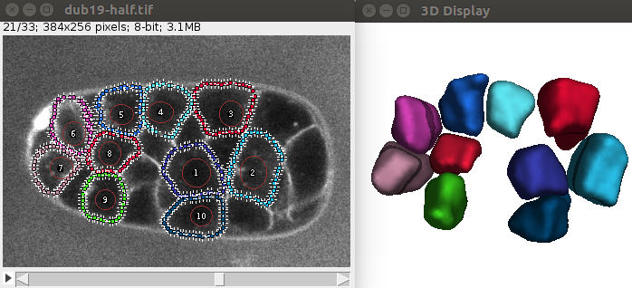
If you want to segment the whole embryo, you’ll need to provide the location of the cell centers, and then launch the command. The following script will segment the demo image for instance using a simple method to identify cells from the nucleus channel:
The colors of cells are chosen randomly and you should be able to vizualize the result both in 2D and 3D, similar to this:
The output table also displays the surface and volume of the segmented cells.
Others commands
Cancelling a segmentation result
To cancel the last launched segmentation command, you can launch the command : Plugins>LimeSeg>Cancel Last Optimisation
The segmentation needs to be stopped before applying this command.
Clearing all segmented objects
- launch the command :
Plugins>LimeSeg>Clear all
Should be used cautiously : this erases all objects segmented by LimeSeg so far.
Stopping a segmentation in progress
- Command
Plugins>LimeSeg>Stop optimization
LimeSeg 3D Viewer (basic)
So far LimeSeg provides its own 3D vizualizer. The 3D viewer looks at a specific point in 3D. Arrows keyboard allow to move this central point. Mouse dragging allows to rotate around this point. Zoom/zoom out can be done with the mouse wheel.
Advanced usage
Graphical user interface
The command Plugins>LimeSeg>Show GUI displays LimeSeg GUI. This graphical interface allows to do almost everything in LimeSeg. Each action (meaning button you click) is recordable if you have opened the Plugins>Macro>Record recorder.
To execute the script in ImageJ 1.x macro language, just add run("Show GUI"); as the first line of your script.
To execute the script in Groovy, replace Ext. by LimeSeg., and put import eu.kiaru.limeseg.LimeSeg; at the beginning of the script.
LimeSeg structure
LimeSeg is composed of multiple parts. It can:
- Manage 3D objects (creation, deletion, copying, pasting, saving, opening…),
- Optimize 3D object shape in relation with an image dataset
- Display these 3D objects both in 2D with point Roi and in 3D with its own vizualizer
LimeSeg 3D objects management
To help understand how LimeSeg does this, please download this sample dataset output (unzip file https://raw.githubusercontent.com/NicoKiaru/TestImages/master/LimeSegOutput/DubSeg.zip).
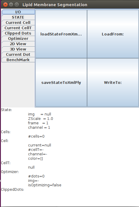
Open Fiji, then launch LimeSeg GUI Plugins>LimeSeg>Show GUI. LimeSeg graphical user interface pops up (click ok on the warning message). The GUI consists of an upper panel that can apply different actions on LimeSeg. Tabs separate the different kinds of objects where actions can be applied. The lower part contains information about LimeSeg state.
To load the sample dataset onto LimeSeg, do the following actions:
-
Unzip the zip dataset sample
-
In LimeSeg GUI I/O tab, click
-
Select the
DubSegfolder that you have unzipped. Click ok. Note that selecting the folder do not open it. To open the data, you need to do the step 4. -
Click
loadStateFromXmlPlybutton in LimeSeg GUI
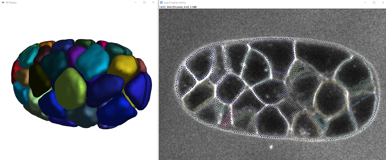
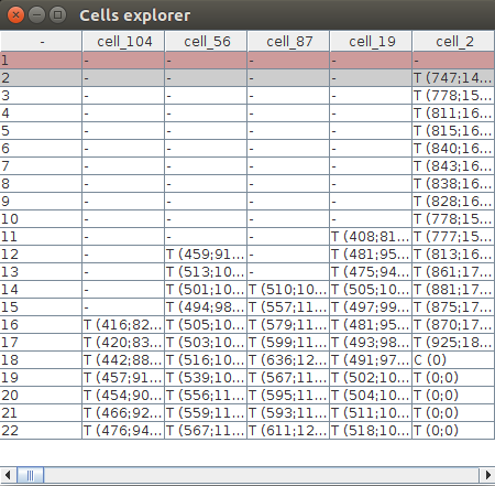
Now click showTable in the STATE tab. This creates a Cells explorer table which shows all the 3D objects segmented by LimeSeg and how they are organized. Each column represents a Cell object which name is at the top of the tab, like cell_2. Rows are timepoints. A cell object may contain many CellT objects, which stands for Cell at a specific Timepoint. For instance, the Cell cell_56 contains 10 CellT objects, for timepoints 12 to 22.
Vizualizing 3D Objects
In LimeSeg GUI, go to 3D View, click make3DViewVisible, then putAllCellsTo3DDisplay. This displays the C Elegans embryo, but only at the first timepoint (timepoint 1 by convention in ImageJ 1.x). However as seen in the table, many more objects exist. To be able to see the evolution of the embryo over time, LimeSeg has to be linked to an ImageJ image (ImagePlus). To link LimeSeg with the proper image, download the image sample https://raw.githubusercontent.com/NicoKiaru/TestImages/master/CElegans/dub-0.5xy-TP1-22.tif and open it in Fiji.
Now you need to link the Image with LimeSeg:
-
Click
Img:in the STATE tab of LimeSeg GUI, and select the image. Click OK. This has no effect at this step. -
Once the image is selected, click
setWorkingImage
Notice that the image name appears in the LimeSeg GUI down panel. You can now browse through timepoints and notice that the 3D Viewer is synchronized with the current displayed timepoint. The 3D Viewer is also synchronized with the z Slice which appears downlighted in the 3D Viewer.
Creating a new Cell
In LimeSeg GUI, click newCell in the STATE tab. You can see that a cell_0 has appeared at the end of the Cells explorer table.
‘Populating’ a Cell
A prerequisite to act on a specific cell is to make sure that it is the current cell (or active cell). The current or active cell name is displayed in the LimeSeg state panel (Cells: current=…) and its column is highlighted in blue in the Cells explorer window. To change the current Cell of LimeSeg you can either:
- Double click on it on the Cells explorer table
- Use the button in the STATE pane (fill in the string id parameter on the right (like
cell_10) before clicking) - Use the button in the STATE pane (fill in the numeric parameter on the right before clicking)
Make sure the current Cell is cell_0. It should be empty. You can check this in the Cells explorer windows. Two ways can be used to populate the cell. Both implies the use of Clipped Dots ‘buffer’ object that will contain either simple shapes or copies of existing CellT objects.
-
Creating a sphere
Go to the
Clipped Dotstab. At the right of the makeSphere button, fill in the 4 white boxes. They correspond to the center of the sphere (x,y,z, radius). All units are in pixel except for z which is in number of slice. Enter 180, 130, 19, 100 for instance. Then click the button. A sphere object has been created in the clipped dots buffer objects. This can be vizualized in the lower panel of LimeSeg GUI (Clipped dots: #dots=). -
Pasting the sphere into a Cell Object
To put the sphere into the current Cell, go to the Current CellT tab, and click
pasteDotsToCellT. Notice that the Cells explorer now displays C(7906) for the currentCell at the TimePoint 1. And the 3D viewer is updated. Now this sphere was pasted at the TimePoint 1, why ? Because LimeSeg has an active or a current frame parameter which is 1 by default. The current frame is another parameter that can be set within LimeSeg. Its current value is displayed in the lower panel of LimeSeg GUI. To change this parameter, go to the STATE tab and in front of the setCurrentFrame button, type 10 for instance. Now click the button. The active frame is now 10. If you now click again onpasteDotsToCellT, the clipped dots (i.e. the sphere) are pasted are the timepoint 10 of the current Cell. -
Deleting a Cell Timpepoint (CellT object)
Set properly the active Cell (see above how to select the active cell) and the active timepoint (STATE > setCurrentFrame).
Click
Current CellT>clearDotsFromCellT
Deleting a Cell
As an example, we will delete the newly created Cell cell_0. First of all, you need to set the cell that you want to delete as the currentCell of LimeSeg.
Click in the tab Current Cell the button .
LimeSeg optimizer usage
To allow for a proper usage of LimeSeg optimizer, the way it can function is modular. To make it work without commands, here are the steps that should be followed:
- Select the 3D image to work with:
- STATE tab > Select the image with the Img: button then click on setWorkingImage
- Choose the correct Timepoint with setCurrentFrame button
- Choose the correct Channel with the setCurrentChannel button
- Set the ratio of Z spacing versus XY spacing. ( For instance 5 for 200 nm per pixel and 1 um per slice).
- Goto the Otimizer tab.
- In the first right box next to setOptimizerParameter, put
Z_scale - In the second, put the correct numeric parameter (1 for isotropic acquisition)
- Click the setOptimizerParameter button (compulsory)
We now suppose that you already have created 3D objects that you want to optimize. Object creation is succintly explained in 3D object manipulation section.
- Now the optimizer knows which image it should use, but there are no 3D objects into it. 3D Objects are called CellT objects in LimeSeg (for cell timepoint). To add such objects into the optimizer, you need, for each object you want to put in:
- Set the current or active Cell as the one you want to use
- Set the current Frame parameter you are working
- Go to the Current CellT tab, and click ‘putCurrentCellTToOptimizer
- Notice in the GUI down panel, the number of dots in Optimizer #dots: should increase
- Set the Optimizer parameters.
- Similarly to
Z_scale,you can set various parameters for the Optimizer f_pressured_0(this should be done before)- and many others… (needs full documentation)
- Similarly to
- You now need to run the optimizer
- In the Optimizer tab, set the number of optimization step you want to perform (-1 means until convergence), then click
runOptimisation
- In the Optimizer tab, set the number of optimization step you want to perform (-1 means until convergence), then click
LimeSeg I/O
3D objects generated by LimeSeg can be saved and retrieved. The structure choice was done with several convention that LimeSeg uses, in order to simplify objects manipulation outside of Fiji.
If you download and unzip the sample file https://raw.githubusercontent.com/NicoKiaru/TestImages/master/LimeSegOutput/DubSeg.zip, you will see that the folder contains an xml file which contains the last segmentation parameters (LimeSegParams.xml) and one folder per Cell object. In each folder, named according to the Cell id object, a CellParams.xml file contains the parameters specific to the Cell object, and CellT objects (Cell at a specific timepoint), consists of files T_x.ply where x is the timepoint number and where ply is the standard 3D format used. PLY (file format) file format is standard and can be used in many other 3D software.
To save the current objects of LimeSeg, choose an EMPTY folder in LimeSeg GUI I/O Tab (Plugins › LimeSeg › Show GUI), with the button , then click on the button.
To open previously saved data, select the folder with the LoadFrom: button then click loadStateFromXmlPly button. This erases all previous data contained in LimeSeg.
LimeSeg 3D Viewer (advanced)
- Image synchronization
LimeSeg 3D viewer is synchronized with the workingImage of LimeSeg state. This image is automatically set by the user selection during a command launch. However, it can also be set within the LimeSeg GUI. To select this image, go to the STATE tab, then choose the proper image by clicking on img, then click on “setWorkingImage” button (do not forget this, otherwise the image selection has no effect).
The synchronization occurs since the current slice is highlighted (downlighted…) in the 3D view in synchronization with the selected slice in the 2D view. Also change frame will change the 3D object displayed in case of a multiframe image.
- Other 3D View parameters.
The other parameters can be modified within the 3D View Panel. In LimeSeg GUI, the command is executed once the user clicks on the left most button. The other text area are parameters that should be specified before clicking the command button.
-
- set3DViewMode If the parameter is 0, all the volumes of the 3D objects are displayed, like this:
1 : the objects are cropped at the position of zposition (cut above)
2 : (cut below)
3 : only the current slice is displayed (cut above and below).
8 : If an optimization is occuring, the optimized dots are displayed (green, dots which have converged, red, dots which have not converged).
Script examples
Example scripts (ImageJ 1.x and groovy) are available here:
They are also accessible as templates in the ImageJ script editor, if the LimeSeg update site is enabled.