Setting Box Counting Options
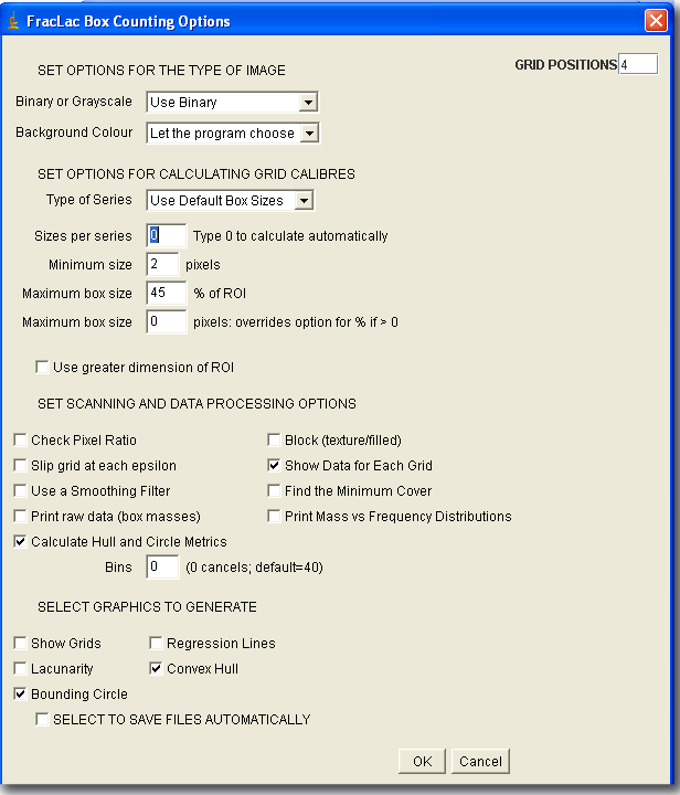
This page describes how to set the options for a Standard Box Count with FracLac. The screen shot below shows the options panel, which this page assumes you already know how to find. If you need to get this panel up in the first place, click here. Note that there is no option for turning off or on the default FracLac Box Counting Results File generated with each scan. Wrong page? I hope I can help. If you need to Interpret Results, click here, or to clarify a term, here. Thank you for visiting, nonetheless, and please accept my best wishes to see you back some day when you are hungry for our wares.To find out what the settings on the panel mean, click a region on the screen shot or scroll down to read the list below it.
Show Grids
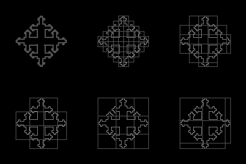
Select this option to make a stack of images showing the actual grids used in a scan. The stack will show at each calibre in a series of boxes laid on an image, the boxes that contained pixels and were counted. The image here was generated using the Make Montage command in ImageJ on the stack generated by selecting this option..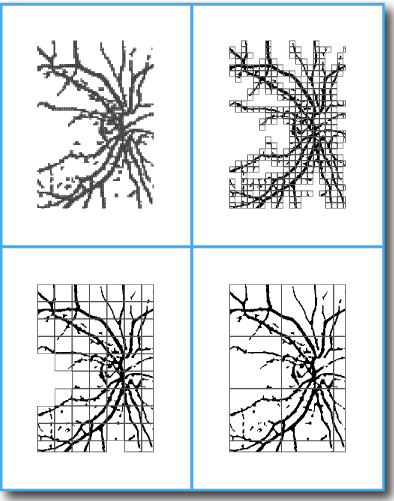
To learn how to make animated images showing grids used, try the grid generating tutorial.
Binary or Grayscale
Choose the type of image and which pixels to assess.
- Select Use Binary to count only foreground pixels in a binary image.
- Select Use Grayscale to find the average intensity of pixels per box in a prepared grayscale image.
- If the images do not match the selected type, FracLac will display an error message and abort.
Number of grid positions
Type the number of orientations to use for the series. Note that the number of grid orientations does not depend on the number of grid calibres in the series.
-
If the number is greater than 1:
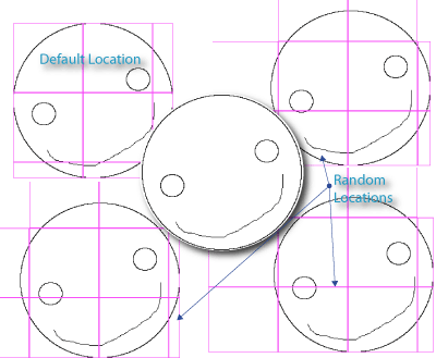
- FracLac does multiple scans based on the 4 corners of the rectangle enclosing the image. The x,y coordinates are randomly generated within the size of the biggest box in the series of grid calibres away from the corners of the bounding box, as in the illustration. If a series of sizes is applied at multiple orientations, as in the example shown here, DBs using average and most-efficient coverings can be calculated. The higher the number of grid positions, the greater the chance of finding a more efficient covering, but only to a point, and the slower the scan where the number of samples increases processing time noticeably for larger images.
-
If the number is 1:
- The grid is laid at the top left corner of the part of the image containing foreground pixels and no average or most-efficient covering is calculated.
-
If the number is 0:
- Just say No! to box counting - only the hull and circle will be found, provided the options for calculating the hull and circle are set, that is.
- Also, you may want to know that:
- The number of sampling orientations used in a scan is reported in the results table.
- You can also find out the coordinates for the orientations used, because they are reported in the Data File (and that is all explained in detail in the tutorial).
Background Colour
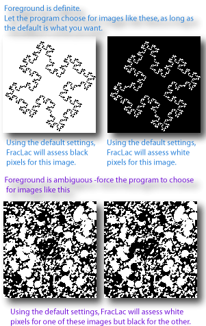
Select Let the program choose to have FracLac determine the foreground and background for binary scans. Foreground pixels are the pixels that are deemed "foreground" by the program, and "background" are all other pixels. The default setting calls foreground white if there are more black than white pixels, and black if there are more white than black pixels.
- In some instances, you will need to select a colour to force the algorithm to count pixels of a certain colour, such as when you are analyzing patterns in which the foreground and background pixels are in similar proportions or when the pattern you want analyzed is not the one that appears to be "foreground" to FracLac. This can be very important for comparing images; if you do not force the choice, FracLac may assess some images in a collection as having a black background and some as having a white background, despite that they may actually have the same colour background, and this can introduce errors in your results. (See the image for an illustration of when to use the default and when to force a choice.)
- This option is ignored for grayscale scans.
glossary entry for foreground pixels
Box Sizes per Series
Set this option to "0" to let FracLac determine the number of grid calibres to use at each sampling grid orientation, or type a number greater than 0 to recommend a length for the series. The number actually calculated also depends on the options selected for Type of Series, minimum size, and maximum size. Note that the number of box sizes actually used is reported in the results table.
Block (texture/filled)
Select this option to scan a square block within an image using a series of grids calculated from the block size. Use this option for some textures, for instance. It keeps the largest box in a scan within the bounding box of the foreground pixels, which excludes from a grid any boxes that would otherwise extend past the bounding box into the margin and be, in essence, partial boxes, which can affect the mean pixels per box. Selecting this option makes FracLac calculate a series of box sizes that divide evenly into the largest size and are no smaller than the smallest ± 5 pixels.
The illustration shows block scans on the left and regular on the right for the same image (centre). All settings were the same for all examples shown, except that the block option was selected for the left and unselected for the right, and the image was scanned without an ROI for the top and with an ROI for the bottom images. The centre image shows the original with the ROI that was used for the bottom scans outlined in magenta, although there was no ROI for the top scans.
This option affects the series of box sizes.
Minimum size
Type a number to set the smallest grid size in the series.
You can affect your results with this setting. One pixel is a logical absolute lower limit on box size but is not necessarily the limit of resolution for the system that created an image. Rather, the box size where no further meaningful detail is available is the practical lower limit in box counting, respecting the relationship between resolution and pixels in a final image. The practical implication for the DB is that the regression line using a box size of 1 pixel will intersect the y-axis (where the ln 1 = 0 is plotted) at the log of the number of pixels of interest, or when expressed using relative scale instead of absolute box size, the intersection will be at a position accordingly adjusted from the number of pixels. Thus, the prefactor, A, depends on the smallest box size used as well as on how the scaling ratio is calculated. Either way, the graph will show the number of pixels counted irrespective of the number of clusters of pixels that are valid at a given resolution.
The option for type of series is also important when determining the smallest size.
Type of Series
Select a type (explained below) from the drop down box to determine how box size changes in a series of grid calibres (the series does not change for each orientation).
- Default (linear)
- The series increases in size linearly by a fixed increment over a range from the minimum to the maximum.
- The increment is set by dividing this range by the number of sizes requested.
- Power
- A dialog box requests a base and an exponent
- the base is raised to the exponent added to itself to make successive sizes
- e.g., for base=2 and exponent = 2.0, the result is 2, 22=4, 24=16, 26=64
- Scaled
- A dialog box requests a maximum, a numerator, and a denominator
- the list is determined by scaling the maximum successively by numerator/denominator and rounding to an integer
- e.g., for maximum = 178 with 1/3, the values are 178×(1/3)=59.3=59, 59.3×(1/3)=19.8=20, etc.
- Relative
- A dialog box requests a value, and the list is determined as factors of that value
- only whole integers are used and no values are rounded, so the list may be short
- e.g., for 32, the series is 1,2,4,8,16,32 but for 31 it is 1,31
- Odd
- Custom
- If "Custom" is selected, a dialog box comes up asking for a comma-separated string of numbers (e.g., 2,4,6,8)
- Duplicates are removed and the list is ordered automatically by the program
Different ways of calculating grid calibres
The series is affected by the number of boxes selected and the minimum and maximum sizes allowed. Also, if the Block Texture option is selected, the series is calculated according to that option. If the series used is not the series you expected, try changing these settings.
Maximum Box Size % of ROI
Type a number for the largest grid in the series as a percentage of image size. This option is overridden if a value is set in the maximum size in the pixels option and is changed by some types of series. Note also that the maximum size is filtered in the value returned as the smoothed DB(small) if smoothing is selected.The actual maximum used is printed in the data file and results file.
Smoothed DB to filter box sizes after the fact
use pixels instead of %
Important Consideration: This option is available as a percentage because box sizes beyond about 50% of the image size introduce errors and to describe an image meaningfully, box size should never exceed the images total size. For sizes greater than 100% of the size of the box enclosing the foreground pixels, the count will always be 1, which will make a slope of 0 for the DB. A scaling ratio greater than 1 (i.e., with a positive exponent) should yield a fractional count, but in FracLac the smallest possible count is the integer 1. All grids of a calibre larger than the smallest box enclosing all the pixels, for a single series of grids having a fixed starting orientation, have count=1 and box size is irrelevant in the equation for slope so the calculated slope is, therefore, horizontal for the interval of all boxes larger than a box containing all the pixels. Indeed, a box count that never goes below this relative size yields a fractal dimension of 0 with undefined correlationi.e., no detected change in detail with scale, regardless of actual scaling in an image. This essential issue also manifests at box sizes approaching the practical upper limit.A range of up to 20 to 50% or the default value of 45% is generally optimal for standard box counting scans.
Maximum Box Size in Pixels
Type a number greater than 0 to force FracLac to use pixels rather than a percentage of image size as the maximum box size.IMPORTANT: SEE Considerations for Maximum Box Size. The actual maximum used is printed in the data file and results file.
Smoothed DB to filter box sizes after the fact
Use Greater Dimension
Select this box to use the larger dimension of the box enclosing the foreground pixels when determining the maximum relative box size.
Show Data
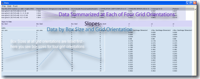
To generate a Data file for each image, in addition to the summarized Results file for all images that is automatically created, select this option with grid orientations≥1. For box counting scans but not multifractal scans, if the number of grid orientations is 0, the option is ignored and no Data file but a Results file and some graphics will be generated.
- As shown in the illustration below, the data file shows:
- an upper section with one row of summarized data for each grid orientation
- a middle part with slopes against ε
- a lower section with the list of εs from the series of grid calibres used then several columns of data for each grid orientation showing data associated with each ε at that orientation
Use a Smoothing Filter
Applies a smoothing filter to the regular calculations to find the smoothed as well as the standard the DB. Calculates the most-efficient smoothed DB if the Minimum Cover option is also selected.
Find the Minimum Cover
Finds the most-efficient covering if the number of grid positions is greater than 1. Calculates the most-efficient smoothed DB if smoothing is also selected.
Slip Grid at Each Position
Selecting this option adds a random factor to grid orientation. If multiple grids are being used, each location for the grid is selected randomly within an area then if this option is selected, the position is further adjusted at scan time.
Print Mass vs. Frequency Distribution
Check this option to generate files showing for each grid and ε the frequencies and masses in the binned probability distribution. This is ignored if bins is < l.  Click the thumbnail to go to the Binned Probability Distribution Page.
Print Raw Data
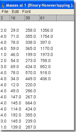
Check this box to generate a file of raw data showing the "mass" or number of foreground pixels in each box at each size in a box count. This is the original raw data used to calculate lacunarity and the DBmass (from the masses) and the DB (from the count of boxes at each size). The screen shot below shows the contents of the file. Along the top are column headings for the box size in pixels, and below each are the actual masses per box at that size. A separate file is generated for each grid orientation.
Bins
Type a number for the number of bins to use for the mass vs. frequency distribution, which is used to calculate the binned probability distribution (BPD) lacunarity; and other BPD values; if this is 0, then no frequency distribution and no BPD data are generated. The image below illustrates a graph of the frequency distributions from the file that can be generated with this option, showing the distribution for each ε at one grid orientation for an image.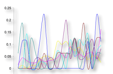
Graph Regression Line
Select this option to see the regression data for the DB graphically as plots and log-log plots of ε and count from box counting. This option will produce a potentially unwieldy number of onscreen graphs; to minimize screen clutter if you select this option, also select the option to save to a folder.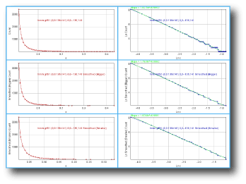
Graph Lacunarity
Select this option to generate graphs of data for lacunarity vs ε.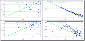
Circle and Hull
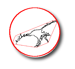
Select these options to calculate other morphometrics along with a standard box count, or set the number of grid orientations to 0 to forego the boxcount scan but still find the hull and circle.
- Select Include Circularity Data to find the convex hull and bounding circle and record circularity, perimeter, span ratio, etc. in the FracLac Box Count Results file.
- Select Draw Hull and Draw Bounding Circle to draw the respective outline on a copy of the original image. Selecting either option will automatically select the option to include circularity data.
- These options are designed for binary contours but will work on other types of binary patterns; they are ignored for grayscale images.
If you are analyzing many files at once, the drawing options will produce potentially unwieldy numbers of new images. In this respect, they are most suitable for single rois on images that are currently open or batch jobs for which the results are being automatically saved.
Check Pixel Ratio
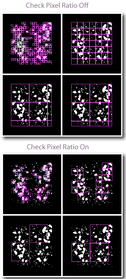
Select to verify boxes in a scan, counting them only if they contain more than a certain ratio of foreground to background pixels. The ratio is
This feature can minimize edge effects on some images (e.g., textures), but can also slow down and change processing considerably. If the ratio is set relatively high, then few or no boxes may be accepted. The results can be checked by looking at the Data file or selecting the option to Show Grids. The image below compares the grids applied with the option selected and with it unselected.
Save Files
Select this option to automatically save data files and graphics instead of showing them on the screen.
Learn about setting up to save files automatically.
