Delete Slice
Deletes the currently displayed slice. You can use Undo to restore it.
Displays the slice following the currently displayed slice. Note that is not necessary
to hold down the command key to use the keyboard shortcut, i.e., you only need to
press the '>' key. You can also use the Page Down key on extended keyboards.
Displays the slice before the currently displayed slice. As a shortcut, use the '<'
or Page Up keys.
Captures a series of video frames into a stack. Before using this command, you must
first create a rectangular selection in the Camera window. The size of this selection
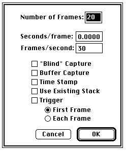
determines the width and height of the stack that will be created. A dialog box allows you to specify the number of frames and the capture rate. The capture rate is specified
by entering either the inter-frame interval (Seconds/frame
) or the frame rate (Frames/second
). Set the inter-frame interval to zero for the fastest capture rate. After Image
has completed recording the movie it will compute the actual frame rate and display
it in the Info window. If the computed and desired rates are not the same then the
frames were probably captured at uneven intervals. In the case, specify a slower
rate, use a smaller selection, or try enabling "Blind" Capture. Type command-period to abort
the movie making process.
Check "Blind" Capture to
disable screen updates, allowing faster frame capture rates.
Captures a frame and adds it to a stack each time the mouse button is pressed. Press
any key to stop capturing.
Animates the current stack by repeatedly displaying its slices (frames) in sequence.
Holding the option key down causes the screen to be erased to the current background
color before the animation starts (or type command-option-'=' as a shortcut). The
animation speed is controlled by pressing keys '1' through '9'. 68040 and Power PC based
Macintoshes using built-in video provide the fastest and smoothest animation. The
right and left arrow keys can be used to single step through the slices. Press the
mouse button to stop. Check Oscillating Movies
in the Preferences dialog box to get Image
to automatically reverse direction at the beginning end of the frame sequence.
Creates an new image that is the arithmetic average of all the slices in the current
stack.
Creates a new composite image from the slices in the current stack.
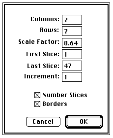
Columns
and Rows
control the number of columns and rows used in the composite image. Scale Factor
determines how the slices in the stack are scaled when they are copied to the composite
image. Decreasing the scale factor makes the composite image smaller and reduces
the amount of memory required. First Slice
and Last Slice
specify which slices in the stack get copied to the composite image. Every slice
(starting at First Slice
) is copied if Increment
is set to one, every other slice if it is set to two, every third slice if it is
set to three, etc. Check Number Slices
to have the slices in the composite image labeled with the slice number. Use the
Font, Size and Style commands in the Options menu (before using Make Montage) to
vary the format of the labels. Check Borders
to draws borders around the slices. The width of the borders can be varied by clicking
on the lines at the bottom of the Tools window. Make Montage normally draws labels
and borders in white. You can force it to use black by setting the pixel in the upper left hand corner of the first slice to white (value = 0).
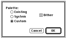
Checking Dither
causes the 8-bit color image to be drawn using error diffusion dithering, a technique
that mixes existing colors to create the illusion of additional colors. Dithering
will usually eliminate color banding in the 8-bit image.
Converts an RGB color image (in the form of a three slice stack) to HSV (Hue, Saturation
and Value).
This routine was written by Michael Castle (mike.castle@umich.edu) of the University
of Michigan Mental Health Research Institute (MHRI).
Distance Between Slices
is the interval, in pixels, between the slices that make up the volume. Image
projects the volume onto the viewing plane at each Rotation Angle Increment
, beginning with the volume rotated by Initial Angle
and ending once the volume has been rotated by Total Rotation.
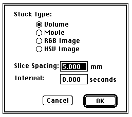
A Volume
is a stack containing a 3D Image. A Movie
is a sequence of frames captured using the Make Movie Command. An RGB Image
is a 3-slice stack containing a 24-bit color image in RGB (Red, Green, Blue) format.
An HSV Image
is a 3 slice stack containing a 24-bit color image in HSV (Hue, Saturation, Value)
format. Slice Spacing
is the distance between the slices in a volume. Interval
is the inter-frame interval in a movie.
Next Slice
Last Slice
Make Movie
Check Buffer Capture
to use uses the LG-3's expandable buffer memory to store the frames. When combined
with blind movie capturing, this enables capturing at video rates. The software
limits the number of frames in a movie to the number which will fit in the LG-3's
memory buffer (this is the number of Mb on the LG-3 times two). Note that if there is a lot
of memory installed on the LG-3, there must also be a lot of system memory in the
Macintosh in order to work with the frames once they are captured.
Select Time Stamp
to have the elapsed time of each frame written in the upper left corner of each frame.
The elapsed times are also stored in the PlotData macro array. See the "Make Movie
and Plot Intervals" macro in "Movie Making Macros" for an example of how to record
and process the elapsed times.
Check Use Existing Stack
to store the frames in the stack last used by Make Movie instead of in a newly created
one.
Triggering can be enabled for only the first frame or for every frame. Check Trigger
and First Frame
and Image
will wait for a mouse press before starting to capture the frames.
The table below shows the maximum frame size for various capture rates when using
a Quadra 700, a Scion LG-3, and "Blind" capture mode. Faster Macs should be able
to capture larger frames at a given rate. The "Frame Rate vs. Frame Size" macro in
"Movie Making Macros" was used to generate the table. The table assumes a 60Hz frame grabber
card that captures at a maximum rate of 30 fps, or .033 seconds per frame. A 50Hz
(PAL) card captures at a maximum rate of 25 fps, or 0.04 seconds per frame.
      Seconds/frame   Frames/second  Maximum Size
          .067             15        320 X 240
          .1                0        480 X 360
          .133            7.5        600 X 460
          .2                5        640 X 480
          .333              3        640 X 480
          .5                2        640 X 480
Capture Frames
Animate
Average
Make Montage
Capture Color
Captures and displays a 24-bit RGB color image. Requires a Scion or Data Translation
frame grabber card and an RGB color camera with separate composite sync output. With
the Scion frame grabber cards, an optional four channel cable is required and Separate Sync
must be checked in the Video Control dialog box. With the Data Translation QuickCapture,
the W5 jumper must be installed and the red, green, blue and sync camera outputs
connected to cables 1, 0, 2 and 4 respectively. Color capture is very memory intensive.
RGB to 8-bit Color
Converts an RGB color image (in the form of a three slice stack) to 8-bit indexed
color. You have a choice of three 256 color look-up tables to use with the indexed
color image. Select Existing
to use the current look-up table. Select System
to use the Apple default 8-bit color table. Select Custom
to create a custom 256 color table based on the colors in the RGB image.
8-bit Color to RGB
Converts an 8-bit indexed color image into a three slice (red, green and blue) stack,
a format that allows filter operations such as smoothing and sharpening to be performed.
Macros are available in the file "Stacks" for automating filtering operations on
RGB stacks.
RGB to HSV
Register
Translates and rotates the slices in the current stack into alignment based on fiducial
points.
There are two interfaces. The more intuitive of the two requires the user to click
on visible landmarks in a reference slice, then click on corresponding fiducial points
in the other slices in the stack. The code then lines up the slices based on these
points. The user may easily throw out unreliable points in non-reference slices and
correct input errors. This registration interface may only be used in cases where
all fiducial points are visible on screen in the captured slices.
The second interface is more difficult to use, but it works regardless of whether
or not fiducial marks are included within the borders of the captured slices. Here,
the user provides fiducial data in a text file. These data consists of relative coordinates of fiducials from each slice as read from a microscope digitizer (or similar device)
as well as the necessary information to map the coordinate system of the microscope
digitizer to the coordinate system of windows in NIH Image.
The text file method uses relative coordinates of fiducial marks as recorded with
some device such as a microscope digitizer. Let us call these coordinates "stage"
coordinates. It also uses screen coordinates of fiducials in Image. Before registration
may take place, stage coordinates must be mapped to the NIH Image screen coordinate system.
To do this, NIH Image reads the following, tab-delimited information from a text
file. In every case, x-coordinates are followed by y-coordinates.
line 1:
the screen coordinates of a point which is fixed for every image captured. In the
sample fiducial file, this is the point which corresponds to the cross hairs on the
microscope at capture time. This is the "image center" point.
line 2:
the location, in screen coordinates, of two fixed points in an image.
line 3:
the location, in stage coordinates, of these same two fixed points.
line 4:
(and each subsequent line) the locations, in stage coordinates, of the "image center"
and at least two, but nor more than 12, fiducial points for an image to be registered.
Obviously, the stage coordinate system may not change in rotation, translation, or
scale in the middle of a set of images being captured, so it is advisable to record
stage coordinates at the time of image capture (without changing camera settings
or the position of the object whose image is being captured).
Lines 4-n must entered in the same order as the slices in the stack. It doesn't matter
which one is the reference image. Where fiducial coordinates are unavailable or unreliable,
use the number 10000 for both the x and y stage coordinate in the file. Each slice must be represented by the same number of fiducial coordinates in the data file.
As you can see, using the text file method introduces many possible sources of errors,
so results are not usually as good with this method as with the on-screen method.
An example stack with text file fiducial points is available at
rsbweb.nih.gov/pub/nih-image/stacks/RegistrationExample.bin
Project
Generates an animation sequence by projecting through a rotating 3D data set onto
a plane. Each frame in the animation sequence is the result of projecting from a
different viewing angle. To visualize this, imagine a field of parallel rays passing
through a volume containing one or more solid objects and striking a screen oriented normal
to the directions of the rays. Each ray projects a value onto the screen, or projection
plane, based on the values of points along its path. Three methods are available
for calculating the projections onto this plane: nearest-point, brightest-point, and
mean-value. The choice of projection method and the settings of various visualization
parameters determine how both surface and interior structures will appear.
This routine was written by Michael Castle (e-mail: mike.castle@umich.edu) and Janice
Keller of the University of Michigan Mental Health Research Institute (MHRI).
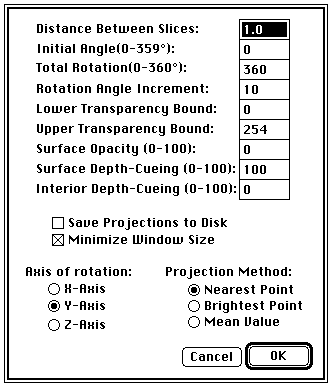
The Lower and Upper Transparency Bound
parameters determine the transparency of structures in the volume. Projection calculations
disregard points having values less than the lower threshold or greater than the
upper threshold. Setting these thresholds permits making background points (those
not belonging to any structure) invisible. By setting appropriate thresholds, you can
strip away layers having reasonably uniform and unique intensity values and highlight
(or make invisible) inner structures. Note that you can use density slicing to set
the transparency bounds.
Sometimes, the location of structures with respect to other structures in a volume
is not clear. The Surface Opacity
parameter permits the display of weighted combinations of nearest-point projection
with either of the other two methods, often giving the observer the ability to view
inner structures through translucent outer surfaces. To enable this feature, set
Surface Opacity
to a value greater than zero and select either Mean Value
or Brightest Point
projection.
Depth cues can contribute to the three-dimensional quality of projection images by
giving perspective to projected structures. The depth-cueing parameters determine
whether projected points originating near the viewer appear brighter, while points
further away are dimmed linearly with distance. The trade-off for this increased realism is
that data points shown in a depth-cued image no longer possess accurate densitometric
values. Two kinds of depth-cueing are available: Surface Depth-Cueing
and Interior Depth-Cueing
. Surface Depth-Cueing
works only on nearest-point projections and the nearest-point component of other
projections with opacity turned on. Interior Depth-Cueing
works only on brightest-point projections. For both kinds, depth-cueing is turned
off when set to zero (i.e. 100% of intensity in back to 100% of intensity in front)
and is on when set at 0<n 100 (i.e. (100-n)% of intensity in back to 100% intensity
in front). Having independent depth-cueing for surface (nearest-point) and interior (brightest-point)
allows for more visualization possibilities.
The Minimize Window Size
option allows you to save memory by making projection windows as small as possible
given the size of the volume and the axis of rotation. If this box is not checked,
projection windows for a given set of slices will be the same size regardless of
the axis of rotation (convenient for animation sequences using multiple axes of rotation).
Select Nearest Point
projection to produce an image of the surfaces visible from the current viewing angle.
At each point in the projection plane, a ray passes normal to the plane through the
volume. The value of the nearest non transparent point which the ray encounters is
stored in the projection image. Brightest Point
projection examines points along the rays, projecting the brightest point encountered
along each ray. This will display the brightest objects, such as bone in a CT (computed
tomographic) study. Mean Value
projection, a modification of brightest-point projection, sums the values of all
transparent points along each ray and projects their mean value. It produces images
with softer edges and lower contrast, but can be useful when attempting to visualize
objects contained within a structure of greater brightness (e.g. a skull).
Several macros (in the file "Stacks") are available for performing various operations
on the slices making up a volume prior to using the Project command. Use "Smooth"
to reduce noise in a volume. Since the projection routine assumes volumes contain
one or more objects within a black background, use "Invert" to invert volumes with a white
background. For low contrast volumes, increase the contrast using the controls in
the Map window and then apply the look-up table to the volume using the "Apply LUT"
macro. The "Remove 0 and 255" macro changes pixel values of 0 and 255 to 1 and 254 respectively.
This is sometimes useful when pseudocoloring projections. Use "Replicate Slices"
to eliminate the gaps seen in projections of volumes with a slice interval greater
than one by increasing the number of slices. The "Make Cone" macro creates a 643 volume containing a cone with two rods inside that is very useful for understanding
the effect of various projection parameters.
Reslice
Reconstructs a 2D image from the image volume contained in the current stack. Use
the straight line selection tool to select were the reconstruction will be done.
You will be prompted for the slice spacing (displacement between slices in the stack)
in pixels if this information has not been previously entered. For experimenting with the
Reslice command, a sample MRI volume consisting of 27 5mm slices is available via
anonymous FTP from zippy.nimh.nih.gov, in the directory /pub/image/stacks. Macros
are available (in the file "Stacks") for repetitive reslicing of image volumes, for example,
to generate a set of coronal slices from an MRI volume consisting of sagital slices.
Stack Info
Allows you to view and set the type, slice spacing, and frame interval of the current
stack.
[Next]
[Contents]
[Home]