Online Manual for the
MBF-ImageJ collection

13 Annotating images
13.1 Scale bar
Scale bars should be present on all publication/presentation images/movies. It’s worth putting them in sooner rather than later. Choose a standard scale bar size for all your images if possible to avoid confusion.
13.1.1 Spatial calibration
The spatial calibration of an image can be found in ImageJ via the menu item “Image/Properties”. It can be manually (re)applied here also. The units ‘um” are automatically changed to “µm”.
Biorad PIC, Noran MOV and Zeiss LSM confocal image files (Leica and Olympus?) are internally calibrated – based on the zoom and objective magnification settings. Some experimental file formats are not calibrated (e.g. Perkin Elmer) and some “exported” image files (e.g. Zeiss zvi’s exported as TIFFs) lose their calibration information. This is sloppy programming on part of the microscope manufacturers and it should be the pointedly drawn to their attention.
If the files have no calibration, you need acquire images of a stage micrometer with the same settings (camera binning, objective, confocal zoom and frame size etc.) as your experiment. The calibration can be applied using the “Plugins/Spatial calibration/Set scale” command (see below). The spatial calibration can be found (and set) in the “Image/Properties” dialog. Also look at the “Microscope scale ” plugin which can be customised to apply spatial calibrations from a drop-down box of objectives (http://rsb.info.nih.gov/ij/plugins/microscope-scale.html).
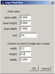
Many image processing functions can cause the spatial calibration to be lost– let me or Wayne Rasband know if you find one and we’ll try to fix it. If the final image has lost its calibration open original file and access the spatial calibration via: “Image/Properties”. Copy these values to the “Image/Properties” of your final, processed image. Replacing the word “micron” with “um” will automatically convert to “µm”.
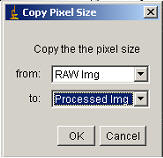
The spatial calibration can be reapplied in three ways: manually via the “Image/Properties” dialog; via the “Plugins/Spatial calibration/Copy Pixel Size ” plugin; or via the “Plugins/Spatial calibration/Set scale” command
13.1.1.1 “Copy-calibration”
|
|
|
|
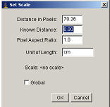
13.1.1.2 “Set Scale”
If you know the size of a feature (previously applied scale bar for instance) you can use this command to apply a calibration.
-
Using the line selection tool, draw a ling along the length of the feature/scale bar.
-
Run the menu command “Plugins/Spatial calibration/Set scale”[1].
-
Enter the dimensions of the object/scale bar in the “known distance” box and set the units in the Unit of length box.
-
Do not check Global unless you wish all your images to have this calibration! Click OK.
13.1.2 Adding scale-bar
|
Use the line ROI tool to draw a line of approximately the desired length and position. Run Scale bar dialog via “Plugins/Spatial calibration/Add Scale bar”[2]. Change the “Width in ***” value to something sensible i.e. 5, 10, 50 etc. Stick to something consistent. “Height” will determine how many pixels fat your bar will be. If you’ve used the “Green” LUT then the “white” (i.e. grey level 255) scale-bar will appear green. Convert the image from 8-bit colour to RGB with “Image/Type/RGB color” before adding the scale bar to get a white scale-bar on a pseudocoloured image (see section 6.9.1). Check the “Label all slices” box to add bar to the whole stack. |
|
13.2 Text and lines
13.2.1 Issues with adding text
Adding text to single frame images should be done in CorelDRAW or some such application so the text does not become part of the image and can therefore be edited/moved/removed at any time. Adding text to an image/movie is irreversible so should not be done on RAW data. Images can be copied to and pasted from the system clipboard between programs using the “Plugins/Utilities/Copy-Paste to clipboard ” panel (hot key: Shift+V) – only available using JRE 1.4 and above. If you find the image is not pasting accurately, try using the receiving application’s “Edit/Paste Special” function and select “Device independent bitmap”.
Firstly, save your images before adding text. Many things can go wrong here and often cannot be corrected so it’s best to have a saved version ready to reopen.
|
Text colour is set via the colour picker button on the tool bar. Double-click on it to pull up the palette and select a colour – usually black or white. Pseudocoloured images should be converted to RGB prior to adding text. The text is “anti-aliased”. This means that instead of being completely white in colour, some pixels on the curved edges of letters are averaged with neighbouring pixels to be grey, giving a smoother appearance to the text. -> The text looks better, however, it means that some of the text’s pixels are not grey-scale value 255 and so some LUTs will have them displayed as yellow/orange/green thereby loosing the nice smoothing effect of the antialiasing e.g. with the Hot Green Blue LUT the counter on frame 1 looks like-> If you use the red or blue LUT then the text will appear red or blue even though you selected the text to be “white” via the colour picker. To avoid this, convert the pseudocoloured image from its current format (i.e. 8-bit color) to an RGB image with “Image/Type/RGB color” before adding the text. e.g. in the example above-> |
|
13.2.2 Adding Text/Line/Box
13.2.2.1 Adding to a single image
Adding a text line or box to a single frame should be done in a package such as CorelDRAW, Adobe Illustrator, Deneba Canvas etc. (see 6.7.1). However, there are times when lines and boxes are required, e.g. to reference an analysed/sectioned region.
Drawing of lines/boxes is achieved by first selecting the desired line/box in the image with the line/Rectangle ROI tool from the toolbar or defining the line/box via “Plugins/Specify ROI… ” or “Plugins/Specify Line… ”. The line/box can be resized here to the desired size/shape with the small square handles on the ROI. The line/box can then be stamped in to the image by right clicking on the image and selecting “Draw”. This will add the box/line to a single frame, the colour determined by the by the color picker toolbar button and the width in pixels defined in “Edit/Options/Line width”.
Adding text is done by the toolbar’s text button. Click the toolbar; click the image; write the desired text. The font size is set by double clicking the toolbar-text button, the colour determined by the by the color picker toolbar button. Antialiasing can be turned on/off via the menu item “Edit/Options/Miscellaneous” (although this option does not affect the `Stamper plugins which have antialiasing on permanently). The text is stamped in to the image by right clicking and selecting “Draw”.
13.2.2.2 Adding to movie-stack
Drawing/writing on a stack only adds the drawn object to the current slice*. If you want the text/box/line to be added to an entire “movie stack” you need to create a new single frame image add the text/box/line to this and then add this single frame to the “movie stack”. This is best done by:
1. Duplicate a frame from the “movie stack” (“Image/Duplicate” and disable “Duplicate entire stack” option).
2. Rename (“Image/Rename”) “text/box/line image”
3. Select the whole image (“Edit/Selection/Select all” or Shift-A)
4. Edit/Clear
5. Go to the “movie stack” and select the desired text/box/line (see 6.7.2.1 above).
6. Go to the “text/box/line image”
7. Restore the selection by “Edit/Selection/Restore” – or Shift-E.
8. Draw the selection (right click the selection and select Draw)
9. Use the Image Calculator (“Image/Calculator”) to add the “text/box/line image” to the “movie image”.
*This may become redundant as ImageJ develops. Keep a look out in the ImageJ/News web page.
13.2.3 Adding timestamps
|
1. Draw a rectangular ROI at the location and of the approximate size of the desired counter. The text will, by default be of the same height as the ROI and aligned to its left edge. Ensure it is not too close to the edge of the image. This will result in a bar underneath the counter e.g. |
|
2. Run the “Plugins/Movies/Time Stamper” .
3. Enter appropriate settings. The X and Y location and font size are taken from the ROI and can be changed at this point.
Remember, the bigger the text, the smoother it will look and the easier the timestamp will be to read. Bigger is better. It may be worth changing it to a consistent value for all your movies.
Also, bear in mind that the interval needn’t be “time". The Time Stamper plugin also can be used to add “z-axis depths” to z-stacks and “angle of rotation” to rotating volume movies ( ° = Alt+247; µ = Alt+230).
13.2.4 Adding event marker to movie
The “Plugins/Movies/Event Stamper” plugin can be used to add text to a movie for a designated number of frames, e.g. “Agonist ON”. This is simply done by running the Event Stamper plugin setting the desired text in the “Text” box, enter start frame and end frame and click OK. The text size and location is taken from the current ROI and can be changed once the dialog is opened.
[1] This simple plugin simply points to the native menu command “Analyze/Set scale…” and is included here to keep the spatial calibration functions in one place.
[2] This plugin simply points to the native menu command “Analyze/Tools/Scale bar…”. It is included here just to keep the spatial calibration functions in one place.