Online Manual for the
MBF-ImageJ collection
10 z-Functions
10.1 Stack-Projections
 A
z-series is generally difficult to represent as a 2-D image for publication
purposes. A montage will allow the 3-D dataset to be visualised in 2-D, but results in
each frame being very small. There are several ways to ‘flatten” the 3D stack.
10.1.1 Maximum intensity Z-projection:
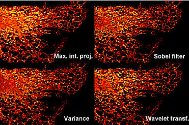
Menu command “Image/Stacks/Z-project” (hotkey: Shift+Z). Select “Maximum Intensity” from the drop-down box. Also look at “Plugins/Stacks – Z-Functions/Grouped ZProjector ” which can be used to perform a “frame average”.
10.1.2 Sobel filter based Focussing
Menu command: “Plugins/Stacks – Z-functions/Stack Focuser ” plugin uses a Sobel edge filter to calculate “best focus”. Try “3” for kernel value in the first instance. Only works on 8- or 16-bit images. It can result in a “pixelly” image.
10.1.3 Wavelet-transform based focussing
Daniel Sage, Jesse Berent, Brigitte Forster, Dimitri Van De Ville, Biomedical Imaging Group, Swiss Federal Institute of Technology Lausanne (EPFL), Switzerland, http://bigwww.epfl.ch/demo/edf/index.html.
Superior, but slower, algorithm compared to the Sobel-filter focussing. Menu command “Plugins/Stacks – Z-functions/ExtendedFocus ” plugin uses a wavelet transform (a more sophisticated transform compared to the Fourier transform) to calculate to “best focus”. Run plugin and click “Fusion” button. Works with RGB images. A full description of the plugin and the can be found at the Author’s website. A topology image is also generated. Please cite the authors papers below if you publish work using this plugin.
|
|
For more information see the following papers:
B. Forster, D. Van De Ville, J. Berent, D. Sage, M.
Unser , "Extended
Depth-of-Focus for Multi-Channel Microscopy Images: A Complex Wavelet
Approach" Proceedings of the Second 2004 IEEE International Symposium
on Biomedical Imaging: From Nano to Macro (ISBI'04), Arlington VA, USA,
April 15-18, 2004, in press. J. Berent, B. Forster, D. Van De Ville, D. Sage, M. Unser, "Extended depth-of-focus for color images in light microscopy using the wavelet transform," Poster at the Autumn Meeting of the Swiss Society of Pharmacology and Toxicology, October 27-28, 2003, Basel, Switzerland.
|
Depth Coding
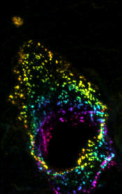
One method of preserving some z-information
in a 2D image is to 'depth-encode' the stack. A monochrome 3D image can be
coloured so that the colour represents the z-depth. Any subsequent projection
will retain this z-encoding. An 8 bit stack can be depth encoded with
the menu command "Plugins/Stacks - Z-functions/Z Code
Stack".
Original
Z Coded
stack

Maximum
Intensity Projections of each

10.2 Volume render
This is a 3D reconstruction method where
the object will appear semitransparent.
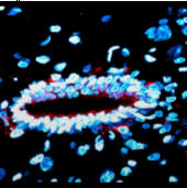
Select the z-series stack then run the menu command: "Plugins/Stacks Z-functions/360° 3D-project". If you want the stack to just rock back and forth use the menu command: "Plugins/Stacks Z-functions/Rocking 3D-project".
Greater control over the settings can be achieved using the menu command: “Image/Stack/3D-Project”.
Try these initial settings:
1. Projection Method: Use “Brightest point” method.
2. Axis of Rotation: Select “y-axis”. There’s a bug which causes errors in x-axis rotation. If you want an x-axis rotation, prior to running the 3D-project command rotate the stack by 90° (Image/Rotate/Flip 90° right), 3D-project, the rotate the projection stack back 90° (Image/Rotate/Flip 90° left). Keep an eye out in the ImageJ/News web page to see if this bug is corrected.
3. Slice Spacing: This determines you aspect ratio of the stack. Biorad stacks are internally calibrated and this value should be correct – unless you set the wrong objective in the Biorad software during acquisition.
4. Interpolate when slice spacing > 0: check this option, although it will slow down the render so for a large data set it may be worthwhile having this “off” while you’re sorting out the settings.
 10.3
Surface Render
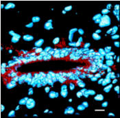
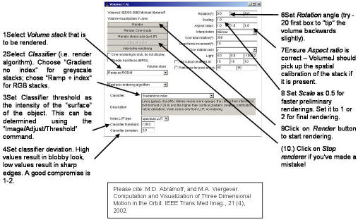
“Plugins/VolumeJ/VolumeJ ”. This is a 3D reconstruction method where the object surface will appear opaque, giving a more “solid” look to the object. See: http://bij.isi.uu.nl/vj_manual.htm and http://bij.isi.uu.nl/vr.htm for updates.
10.4
Axial-sectioning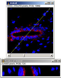
This generates a “side-view” of a stack along a user defined line. Select part of stack to be axially sectioned using the line ROI tool from the toolbar. Select menu item:
“Image>Stacks>Reslice .
The line can be restored using the menu item “Plugins/ROI/SpecifyLine ”.
This approach can be used to generate 'linescan' type images from an XYT series.
A polyline can be used although this will only allow a single pixel slice to be made.
10.5 Orthogonal views
“Plugins/Stacks – Z-functions/Volume
View will
allow users to display the xy, x,z and yz views of a selected point in the image (click on desired point).
After selecting a point a Volume View can be generated with the Ortview
plugin’s menu command “Options/Volume View”. This will open an ImageJ
window
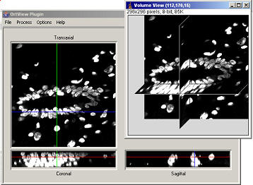 with
the volume image.The stack can be smoothed with various algorithms selected from
the “Process” menu. One of the algorithms is a 2x2x2 smooth. This will
take in to account adjacent slices and may be the best way to gently smooth stacks.
The smoothed stack can be sent to an ImageJ window for subsequent processing,
analysis or export via the OrtView menu command
“File/ExportImages/Export Transaxial Stack”
A fuller description of the plugins capabilities can be found in the OrtView help file (found in the folder: C:\ImageJ\Plugins\Stacks – Z&T functions\OrtViewHelp.txt). The plugin is easy to use but limited to grey-scale images (8- or 16-bit) due to its nuclear medicine heritage.
10.6 Stereo Pairs and Anaglyphs
10.6.1 Volume rendered-anaglyphs
These plugins are under development and are at an early stage – please send feedback to tonyc@uhnresearch.ca.
This is an adaptation of the methods described at: http://rsb.info.nih.gov/nih-image/more-docs/confocals.html.
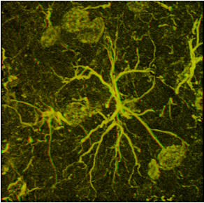
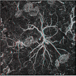
The menu command “Plugins/Stacks – Z-functions/Stereo pair ” plugin will create a side by side stereo pair from your stack and also a red-green anaglyph. The plugin will let you specify which of the stereo pair projections you want and also the angle of rotation between the pairs. Typical values would be 6-9°.

Stereo Pair
|
|
|
|
Red-Green Anaglyph |
Red-Cyan Anaglyph |
10.6.2 Surface rendered-anaglyphs
Surface
stereo pairs are simply made with VolumeJ’s stereo pair button. This generates
a stereo pair with a 5° difference.
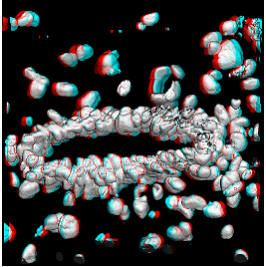
These two images can be merged to form an anaglyph using either the menu command “Plugin/Colour Functions/Colour merge” or “Image/Color/RGB merge”.
The “left eye” needs to be red; the “right eye” cyan or green.
Surface rendered anaglyph movies can be constructed using VolumeJ following an approach from Harvey Karten and Joel Sheffield.
1. Surface render your z-series (see Section 10.3 Surface Render) with a “Cine frame increment” of 6-9°.
2. Duplicate the Surface rendered movie.
3. Delete the top slice from the original movie.
4. Delete the last slice from the duplicate movie.
5. Merge the stacks using the menu command “Image/Color/RGB merge”.
6. Assign the duplicate stack as red and the original stack as green. For Red-Green anaglyphs set blue to be none; for red-cyan anaglyphs set the blue channel to be the same as the green.

