FociPicker3D 3D and 2D particle counter
Author: Guanghua Du, gh_du(at)impcas.ac.cn, Institute of Modern Physics, CAS, China
History: 2012-01-16: Second Version; 2010-04-16: First Version (multi-thead)
Source: Foci_Picker3D.java
Installation: Download the two class files Foci_Picker3D and PixelCollection3D to the plugins folder or a subfolder, and copy the lookup table FociPicker_256Colors.lut to the luts folder of ImageJ, then restart ImageJ or use the menu selection Help > Update Menus. The lookup table is used to render the foci mask in the output image.
I: Description:
The FociPicker algorithm is based on the following assumptions: a) Each focus is represented by one and only one local maximum center; b) a maximum center is one pixel or a group of continuous pixels with the same intensity (Hi) which is bigger than all the surrounding pixels). The algorithm has two input parameters as defined below:
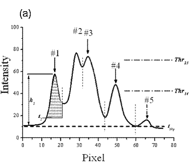
1)Background tbkg--the background intensity around a focus. Given the tbkg, the intensity range of the ith maximum is calculated by hi = Hi-tbkg.
2)Fraction f --a threshold in percentage that defines the brightest fraction of a focus. This means the ith focus contains only pixels have intensity between (Hi-f·hi) and Hi, where (Hi-f·hi) is called as a local threshold ti.
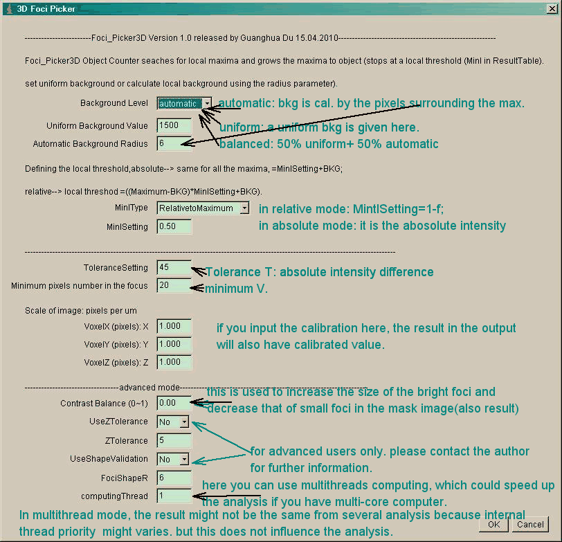
The background level tbkg can either be given as a uniform background which is used for all objects, or be calculated by the program (i.e, the algorithm picks up the dark pixels in surrounding of a given radius, which means each object has a local background).
As shown in Fig. 1a, the algorithm first searches for the maximum centers, and expand from the center until it reaches to the edge of the focus, which is defined by the local threshold ti or minima pixels (valley). The volume, area, intensity and coordinates of these recognized objects (foci) are analyzed, and the results are stored in an Excel table. At the same time, the objects are shown with different colors in a separate image stack.

After the foci are recognized, the results could be filtered by several conditions:
1) Tolerance T--defines the minimum intensity range of the pixels inside the focus (a focus contains pixels of only one intensity value will give a T=0).
2) Minimum V--defines the minimum volume/area (in pixel number) one focus contains.
3) FociShapeR (optional)--defines the mimimum radius of the particle recognized.
II: Interface

III: Result

IV: Example
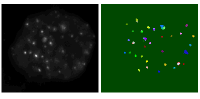
download the 3d stacks of a foci image (16 bit) (see bottom left), open with ImageJ, set the ToleranceSetting to 2000, keep other parameters as default, then run the plugin. after 1 seconds, you will get a mask image of the foci (bottom right), and a resull table. both images here are max-projection.

V: Reference
1. G. Du, G. A. Drexler, W. Friedland, C. Greubel, V. Hable, A. Kugler, R. Kr��cken, L. Tonelli, A. A. Friedl and G. Dollinger. Spatial dynamics of DNA damage response protein foci along the ion trajectory of high-LET particles. Radiation Research 176,706-715 (2011)